HF Yagi benchmarks – what commercial designs achieve
What commercial and published HF Yagis achieve for a given boom length, what theory says about the limits, and how far the published figures can be trusted.
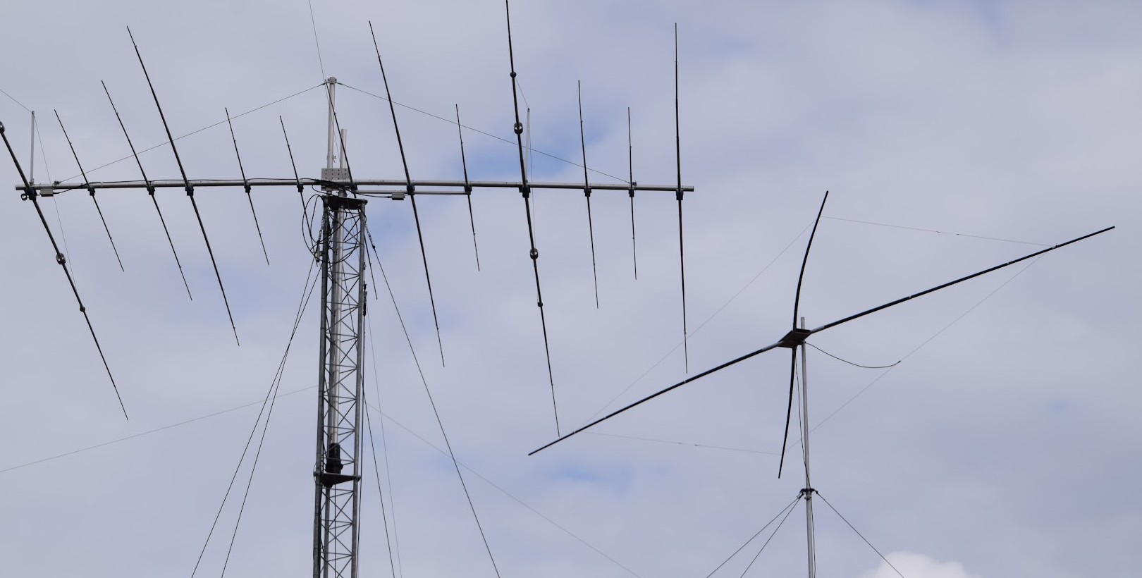
What limits the gain of a Yagi
Five results from the literature frame what a design on a given boom can reach. Numbers in brackets point to the references at the end.
The boom length sets the gain
Lawson (W2PV) showed that the gain of a Yagi depends mainly on its boom length and much less on the number of elements [2]. The NBS measurements of optimized Yagis give 7.1 dBd on a 0.4 λ boom, 9.2 dBd on 0.8 λ, 10.2 dBd on 1.2 λ and 14.2 dBd on 4.2 λ [1]. The NBS data add dB and today's commercial HF monobanders dB for each doubling of the boom.
Long booms approach the end-fire limit
A Yagi is an end-fire array. For a uniform end-fire line of isotropic elements the directivity grows as D ≈ 4 L/λ with ordinary phasing and D ≈ 7.16 L/λ with the Hansen–Woodyard phase condition [3] [4], which is 3 dB per doubling of the length. The director chain of a real Yagi does not hold the ideal phase velocity over the whole boom, so long Yagis gain less per doubling than this.
Short booms are limited by superdirectivity, not by length
For N closely spaced elements the directivity can in theory approach N² (Uzkov [5]; Harrington generalized it to N² + 2N for multipole sources [6]): 6.0 dBi for two and 9.5 dBi for three isotropic radiators, whatever the boom length. The two-dipole case is analysed in [7]. Getting close to the limit needs small spacing, strong opposing currents and a low radiation resistance, so the antenna becomes narrow-band and conductor losses eat the gain. Even Cebik's maximum-gain 3-element models have feed resistances of only 25–27 Ω [11]. DK7ZB designs his HF Yagis for a 28 Ω feed with a quarter-wave matching section, and they lie 0.2–0.4 dB above the commercial 50 Ω trend [23]. HF designs with a direct 50 Ω feed and a low SWR over the whole band therefore stay below the maximum-gain curve. Compact two-element beams show the other side of the limit: the Moxon rectangle reaches about 5.8 dBi in free space on a depth of only 1/8 λ [25], and hexbeams 5.6–5.9 dBi [26], close to the 6 dBi of two isotropic radiators.
On a given boom, gain, F/B and bandwidth trade against each other
Cebik's NEC models of 3-element Yagis on 0.22, 0.29 and 0.33 λ booms give 7.1, 7.8 and 8.1 dBi with a 180° F/B of 42, 35 and 27 dB [11]; he also warns that the 180° figure flatters the short design. SteppIR quotes 9.7 dBi with about 20 dB F/B for a 3-element Yagi on 0.4 λ, 8.6 dBi with up to 35 dB on 0.25 λ, and calls 0.3 λ the best compromise [12].
Optimization methods
Cheng and Chen optimized the element spacings by perturbation [8]; Cheng later perturbed spacings and lengths together and reported gain increases of nearly 80 % over the starting arrays [9]. Jones and Joines used a genetic algorithm with NEC-2 [10]. K6STI's Yagi Optimizer is used by makers such as M2, who state that its results agree with NEC within a few hundredths of a dB [13]. These methods maximize the gain at one frequency. An HF design also has to hold SWR and F/B over the whole band, which costs part of that gain.
Gain against boom length: theory, measurement and products
Logarithmic boom axis. The end-fire curves are for isotropic elements; the dipole elements of a Yagi add their own directivity, so these curves show the slope rather than the level. NBS values were measured at 400 MHz and converted with dBi = dBd + 2.15.
Key findings
Gain follows boom length
Full-size commercial monobanders on all bands from 40 to 10 m lie on one curve when the boom is measured in wavelengths. The scatter around it is about ±0.5 dB; the best designs sit 0.5–0.7 dB above it.
Free-space gain against boom length
Multiband antennas are plotted per band with the whole boom, although the 15 m and 10 m elements use only part of it. Hover a point for details.
F/B depends on how it is measured
Makers publish one F/B number without a definition, often as a “> 25 dB” limit. It is usually the value straight behind (180°) at one frequency. The worst rear lobe in a 120° sector over the whole band, as MMANA-GAL reports it, is often 5–13 dB lower for the same antenna, and Cebik warns that the 180° figure can flatter a design [11]. Compare published F/B values only roughly.
F/B against boom length
Recommended targets
Goals for new designs and for the optimizer. Gain goals are in free space; over ground at 12–22 m on 20–10 m add about 5 dB (table below).
How the numbers were made comparable
- OptiBeam publishes “average gain over a dipole in free space” in dBd. Free-space dBi = dBd + 2.15.
- Antennae Depot publishes dBi at 22 m from MMANA. The ground gain of a Yagi at 22 m over ε 13 / 5 mS/m, computed with a MININEC 3 model (MMANA-GAL conventions), is subtracted. Their own dBd figures agree with this within 0.1–0.35 dB.
- Boom is divided by the wavelength at the band centre: 7.1, 14.175, 21.225 and 28.5 MHz.
- The trend is a least-squares fit of G = a + b·log10(boom/λ) to the 30 full-size commercial monobanders with gain data. Shortened 40 m antennas are shown but not fitted.
- SP7GXP lists dBd and dBi for each model, and the dBi is always exactly dBd + 7.15, i.e. over ground; dBd is taken as free space. For two 5-band models (3 and 4 elements) the dBd lie 2–3 dB above the trend and above GXP's own larger antennas; they are plotted as published (hollow) with a note. SteppIR DB36 dBi are taken as free space; its elements are re-tuned for every frequency, which a fixed Yagi cannot do. Cebik's 3-element designs are NEC models in free space.
- OptiBeam and Antennae Depot have their own colours; the other makers and designers share a grey and the tooltip names them.
- DK7ZB gives dBd at the start, middle and end of each band without naming the reference; his pattern plots are free space, so the mid-band dBd + 2.15 is taken as free space. Only the 10, 15 and 20 m designs are included.
- N6BV (designs from the ARRL Antenna Book, published with dimensions by Cebik), W6NGZ and the Moxon rectangle are NEC models in free space. W6NGZ is only given as “over 10 dBi”, entered as 10.0.
- Hexbeams (EAntenna HEX6B, G3TXQ broadband design) have bent elements on a hexagonal frame and no boom; the hexagon diameter, 6.50–6.52 m (twice the turning radius), is used as the boom length, i.e. the whole depth in the beam direction, as for the Moxon rectangle. The centres of the driven element and reflector are only about 1.3 m apart [25], so neither measure is a true boom. The G3TXQ figures are reported by M0OXO as modelled at 6 m above ground, so they are plotted as published (hollow); dBd + 2.15 equals the free-space values that EAntenna gives for the HEX6B. Measured this way a hexbeam lies about 1.8 dB below the trend on 20 m and further below on 15 and 10 m, where the smaller nested elements use only part of the frame, as with the higher bands of a tribander. The hexbeam buys its small turning radius with gain.
- Published .maa models (MMANA-GAL example library and handiko's own models, from the GitHub repository handiko/AntennaFiles-OLD [27]) are not quoted but computed with one program: MININEC 3 with MMANA-GAL conventions, free space, at the band start, centre and end. Gain is the mean of the three, F/B the 180° value at the band centre (the worst case over the band is in the notes). Several library models are tuned for one frequency and have a high SWR at the band edges; the notes say so. The 3-element 20 m library model uses an old taper format that could not be read reliably and is left out; Moxon geometry has not yet been validated against MMANA-GAL.
- M2 and Cushcraft XM240 publish free-space gain (M2 on scanned data sheets, read off the scans).
- Hy-Gain and Cushcraft tribanders give dBi without saying what it refers to, often as a maximum or as one figure for all bands. These are plotted as published with a hollow marker.
- Gain over ground without a usable boom length, or one figure averaged over five bands (Spiderbeam, InnovAntennas, EAntenna), is listed in the database but not plotted. EAntenna's “max” figures lie about 5 dB above the free-space trend, so they are taken as over ground.
- JK Antennas, Mosley and Force 12 publish no gain figures that could be found.
Limits of published data
Read the commercial figures as upper bounds.
Optimistic for marketing
Some published figures are better than the antenna. M2 warns in its own manual that spec sheets may quote dBi instead of dBd (2.14 dB more), include up to 6 dB of ground gain, or simply be raised by the marketing department [13]. F/B is usually one best value without a definition. Example: the Hy-Gain TH3-MK4 is specified with 8.0 dBi on a 4.3 m boom, 1.7 dB above the trend for 20 m.
No model to check
For most commercial antennas no simulation model is published: no element dimensions, tube tapers or spacings for NEC or MMANA-GAL. Their figures cannot be checked by an independent calculation. In this database only the designs of DK7ZB, N6BV, YU7EF and Cebik come with dimensions, and only the MMANA-GAL library and handiko models come as ready .maa files, which were recalculated here.
Not measurable in practice
Differences of a few dB cannot be measured reliably with amateur means. An S-unit is nominally 6 dB and S-meters are rarely calibrated, HF signals fade by 10 dB and more within seconds, and height, ground and surroundings change the pattern. A real comparison needs a test range or careful A/B measurements against a reference antenna.
A fair comparison therefore needs a published model that can be recalculated in one program. Without it, the figures in this overview are taken at face value.
Database
Free-space gain and boom in wavelengths per row; the model name links to its source. Hover a row for the published figures and notes, click a column to sort. The filters above apply; a highlighted maker filters the table to that maker. * multiband, values for that band.
References
All web sources were accessed and the data collected on 9 November 2026. The data set and the scripts are in the OK1M-PyminiNEC3 repository (docs/benchmarks).
Theory and design literature
- [1]P. P. Viezbicke, “Yagi Antenna Design,” NBS Technical Note 688, National Bureau of Standards, 1976. tf.nist.gov/general/pdf/451.pdf
- [2]J. L. Lawson, W2PV, Yagi Antenna Design, ARRL, 1986.
- [3]W. W. Hansen, J. R. Woodyard, “A new principle in directional antenna design,” Proc. IRE, vol. 26, no. 3, pp. 333–345, 1938.
- [4]N. K. Nikolova, “Lecture 14: Linear array theory, part II” (end-fire and Hansen–Woodyard directivity, eqs. 14.38–14.45), McMaster University, 2025. ece.mcmaster.ca
- [5]A. I. Uzkov, “An approach to the problem of optimum directive antenna design,” Comptes Rendus (Doklady) de l’Académie des Sciences de l’URSS, vol. 53, 1946.
- [6]R. F. Harrington, “On the gain and beamwidth of directional antennas,” IRE Trans. Antennas Propag., vol. 6, no. 3, pp. 219–225, 1958.
- [7]P. Hazdra, J. Kracek, T. Lonsky, “On the end-fire (super) directivity of an array of two elementary dipoles,” arXiv:1804.05876, 2018. arxiv.org/abs/1804.05876
- [8]D. K. Cheng, C. A. Chen, “Optimum element spacings for Yagi-Uda arrays,” IEEE Trans. Antennas Propag., vol. 21, no. 5, pp. 615–623, 1973.
- [9]D. K. Cheng, “Gain optimization for Yagi-Uda arrays,” IEEE Antennas Propag. Mag., vol. 33, no. 3, pp. 42–46, 1991, doi:10.1109/74.88220.
- [10]E. A. Jones, W. T. Joines, “Design of Yagi-Uda antennas using genetic algorithms,” IEEE Trans. Antennas Propag., vol. 45, no. 9, pp. 1386–1392, 1997, doi:10.1109/8.623128.
- [11]L. B. Cebik, W4RNL, “I want to build a 3-element Yagi” (NEC models of K6STI and K9EUV designs). antenna2.github.io/cebik
- [12]SteppIR Antenna Systems, FAQ (boom length of a 3-element Yagi). consumer.steppir.com/support/faqs
- [13]M2 Antenna Systems, 20M5 manual (“The inside story”: K6STI Yagi Optimizer, inflated specifications). m2inc.com
Antenna data
- [14]OptiBeam antenna overview and product pages. optibeam.net/antennen
- [15]Antennae Depot, HF monobanders 40 m, 20 m, 15 m, 10 m and multibanders.
- [16]SP7GXP antennas, product pages at sp7gxp.pl/antennas (each database row links to its page); 2026 models also via cq.sk: 2026 models, model overview.
- [17]SteppIR DB36 specification sheet, Rev 10.23, 2023. consumer.steppir.com
- [18]D. Dobričić, YU7EF, EF154C 4-element 21 MHz Yagi. yu7ef.com/ef154c.htm
- [19]M2 Antenna Systems data sheets: 20M5, 20M4DX, 15M4DX, 15M6DX, 10M7DX.
- [20]Hy-Gain manuals: TH3-MK4, TH-11DX; TH-7DX: mfjenterprises.com and WiMo listing.
- [21]Cushcraft catalogue sheets: A3S / A4S / A3WS, XM240.
- [22]Spiderbeam 20-15-10 HD, shop.spiderbeam.com; InnovAntennas XR5, innovantennas.com; EAntenna DX-Predator, WiMo listing.
- [23]M. Steyer, DK7ZB, “3-, 4- and 5-element Yagis for the 10 m, 12 m, 15 m, 17 m and 20 m band” and 2-element 20 m Yagi. qsl.net/dk7zb, 2-element 20 m.
- [24]L. B. Cebik, W4RNL, “Some larger 10-meter Yagi designs” (No. 29: N6BV designs from the ARRL Antenna Book, with dimensions). antenna2.github.io/cebik; “Modeling 6 long-boom Yagis” (20 m, W6NGZ, K6STI, W3LPL, K4SB, NW3Z, WB0DGF). antenna2.github.io/cebik
- [25]L. B. Cebik, W4RNL, “Designing Moxon rectangles by equation and by model” antenna2.github.io/cebik and “A tale of 4 beams: the X, the hex, the square, and the rect” antenna2.github.io/cebik.
- [26]Hexbeams: EAntenna HEX6B, WiMo listing and MHzOutdoor (radius 3.26 m); S. Hunt, G3TXQ, broadband hexagonal beam, figures as reported by M0OXO, radius from cq.sk.
- [27]H. Gesang (handiko), AntennaFiles-OLD: MMANA-GAL and 4NEC2 model collection including the MMANA-GAL example library (folder ANT), GPL-3.0. github.com/handiko/AntennaFiles-OLD. Models recalculated with docs/benchmarks/compute_maa_library.py.
Every row of the database also links to its own source page.
This analysis was made to get a reference picture for developing my own antenna optimizer, but it turned out so interesting that it is worth publishing.
73 Michal OK1M