OK1M 7-element multiband Yagi for 20/15/10 m
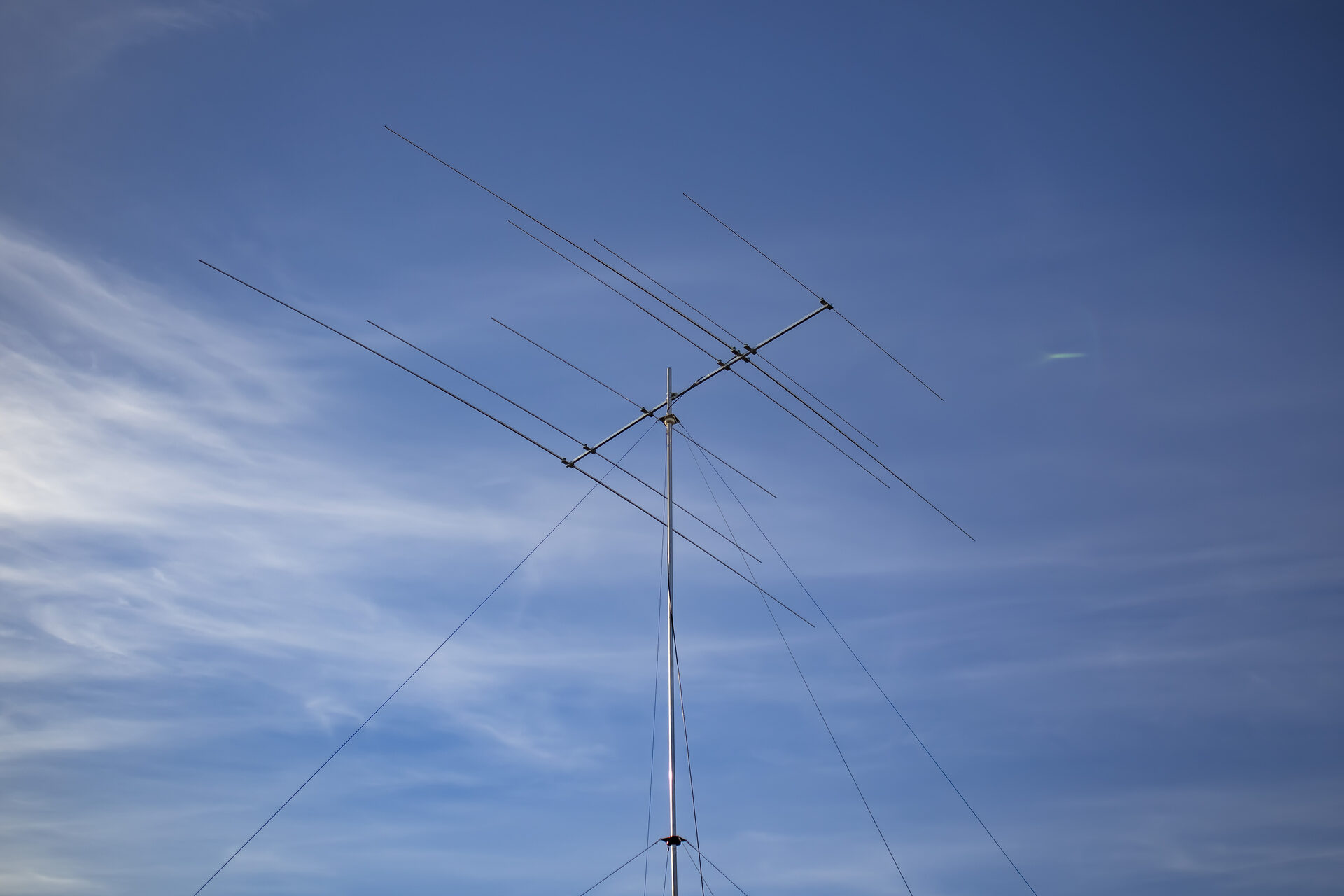
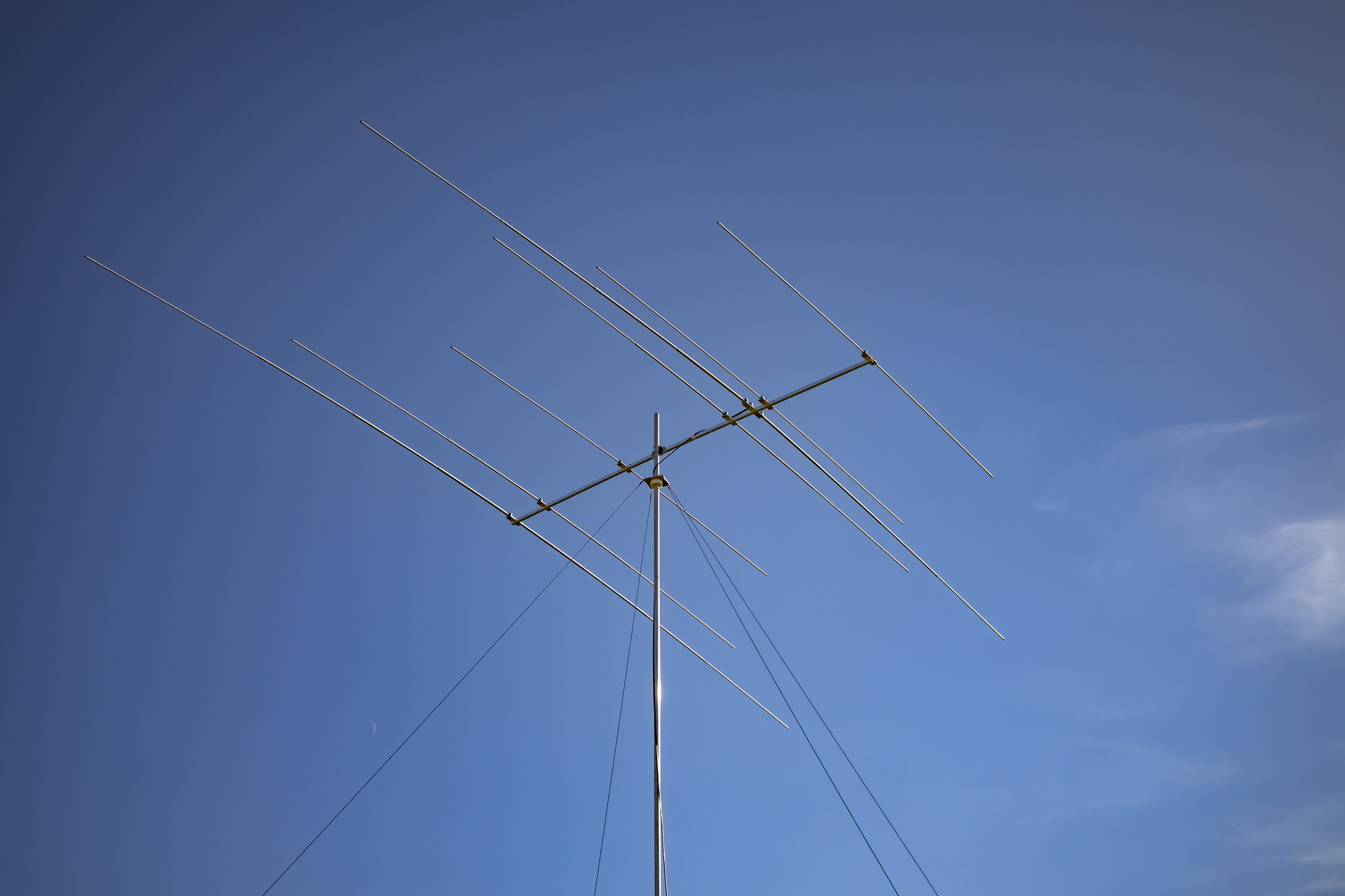
A 7-element multiband antenna for contesting on the 20, 15 and 10 m bands: 2 elements on 20 m, 2 on 15 m and 3 on 10 m, all on a 4.36 m boom with a single 50 Ω feed line. It is a shorter sister of the 9-element version.
Design
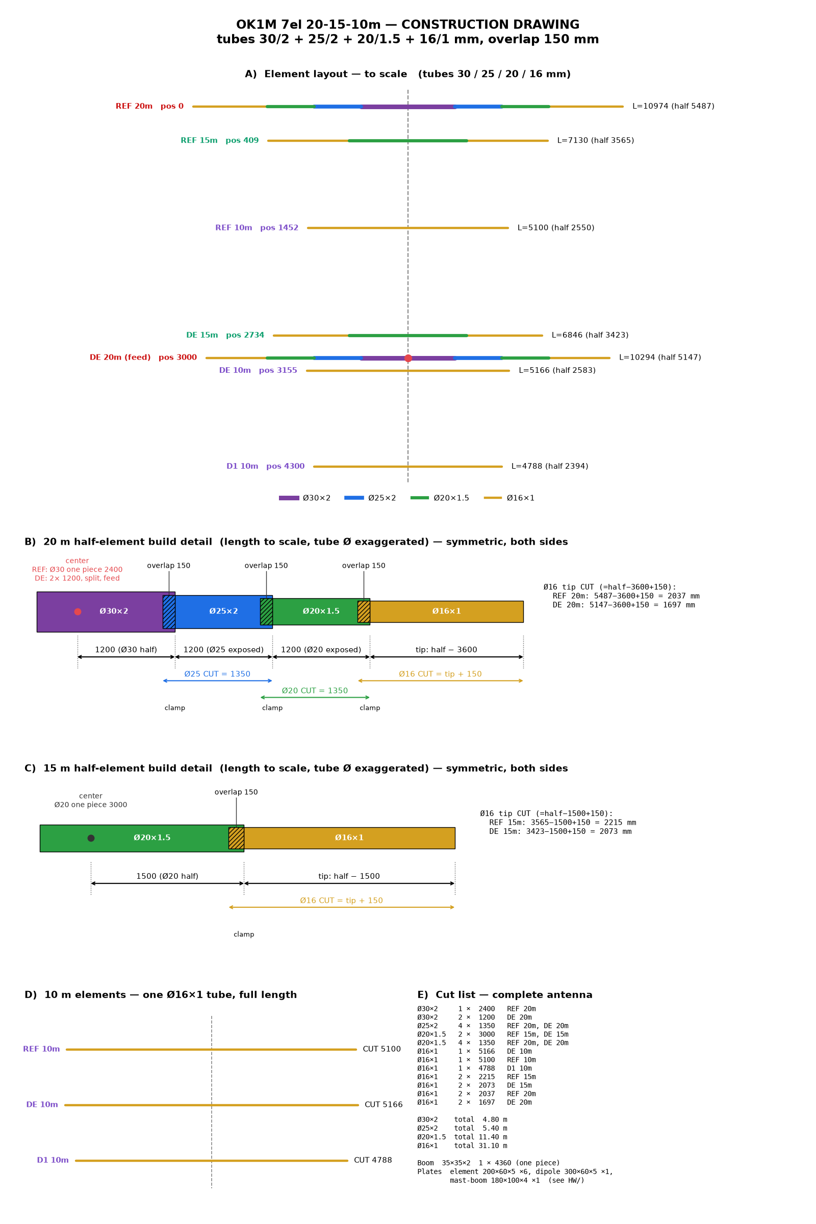
Only the 20 m driven element is fed. It is split in the centre, and the 15 m and 10 m driven elements are continuous open-sleeve elements coupled from it. The antenna was modelled and optimized with OK1M-PyminiNEC3 for flat SWR across 14.000–14.350, 21.000–21.450 and 28.000–28.700 MHz.
Computed performance
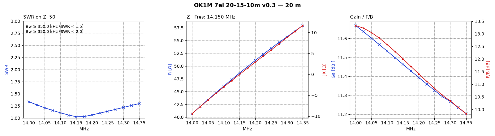
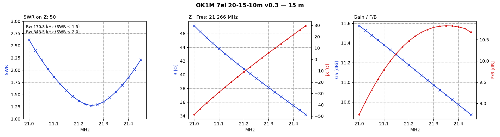
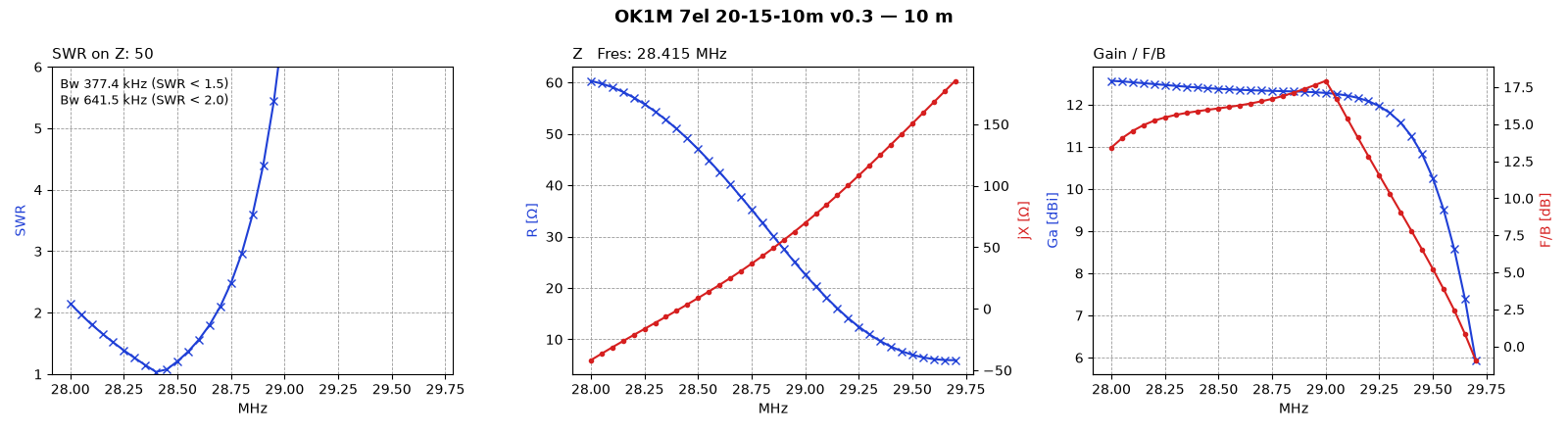
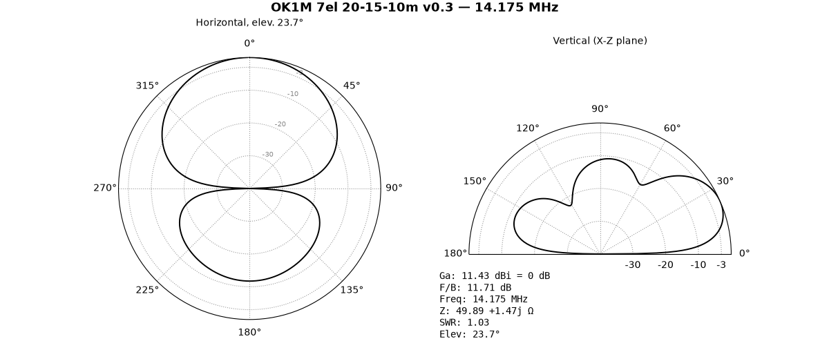
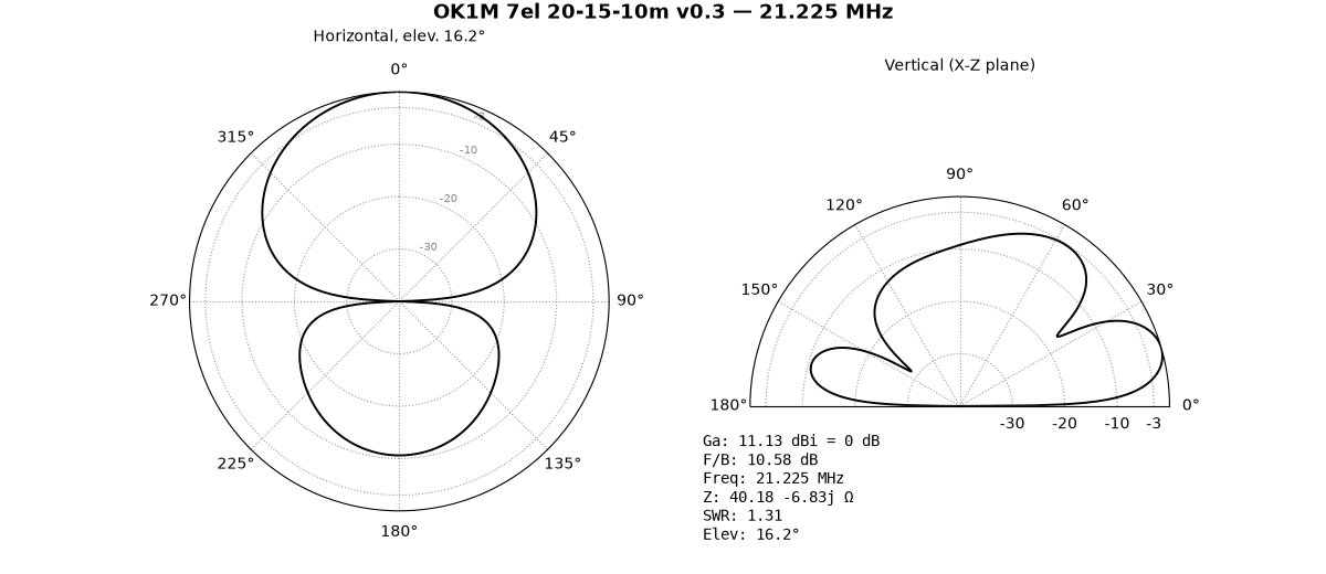
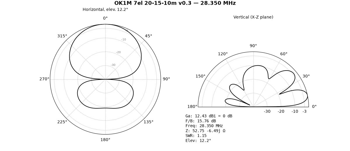
Model v0.3, 12 m above real ground (ε = 13, σ = 5 mS/m):
| Band | Elements | SWR | SWR < 2 | Ga [dBi] | F/B [dB] | Elevation |
|---|---|---|---|---|---|---|
| 20 m | 2 | 1.03–1.34 | whole band | 11.2–11.7 | 9.8–13.3 | 23.7° |
| 15 m | 2 | 1.27–2.62 | 21.079–21.423 | 10.7–11.6 | 8.7–10.8 | 16.2° |
| 10 m | 3 | 1.04–2.15 | 28.042–28.683 | 12.3–12.6 | 13.4–16.5 | 12.2° |
The upper part of the 10 m band is outside the optimized range – SWR reaches 6.8 at 29.0 MHz.
Elements
| Element | From boom rear end [mm] | Length [mm] | Tubes [mm] |
|---|---|---|---|
| REF 20 m | 30 | 10 974 | 30 / 25 / 20 / 16 |
| REF 15 m | 439 | 7 130 | 20 / 16 |
| REF 10 m | 1 482 | 5 100 | 16 |
| DE 15 m | 2 764 | 6 846 | 20 / 16 |
| DE 20 m (feed) | 3 030 | 10 294 | 30 / 25 / 20 / 16 |
| DE 10 m | 3 185 | 5 166 | 16 |
| D1 10 m | 4 330 | 4 788 | 16 |
Construction
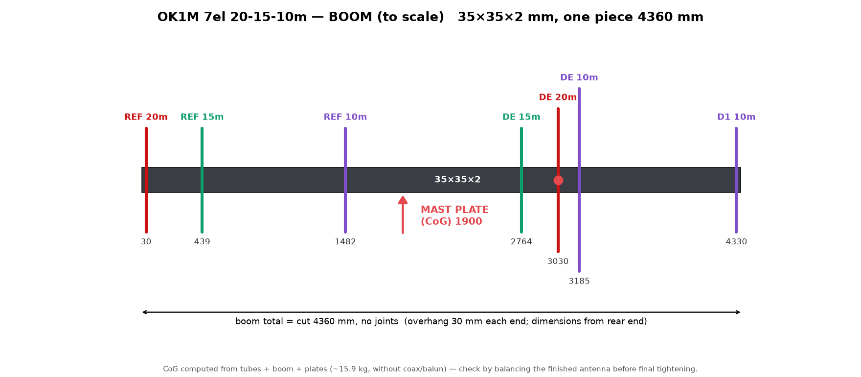
- Boom – 35×35×2 mm, one piece 4 360 mm without joints, 3.1 kg
- Elements – telescopic aluminium tubes with a 150 mm overlap, tightened with hose clamps
- Insulators – polypropylene tube clamps on laser-cut aluminium plates
- Mast plate – at the centre of gravity, 1 900 mm from the rear end of the boom
- Feed – 1:1 current balun at the 20 m driven element
- Mass – approx. 15.9 kg without coax and balun
Documentation
The repository contains the MMANA-GAL models, the full bill of materials with a cutting plan, drilling drawings and DXF files of the plates.
- Repository: git.ok1kvk.cz/RybkaLabs/multiband-hf-antenna-7el-ok1m-20-15-10m
- Web documentation: ih9.ok1m.cz/antennas/ok1m-7el-multiband
Update: the antenna was used at 12 m at IH9/OK1M – see the report from CQ WW DX SSB 2026.
73 & TNX