144 MHz LNA with PGA-103+ in an aluminium case
A low noise amplifier for the 144 MHz band built around the PGA-103+, with a low pass filter at the input, a band pass filter at the output and two bypass relays, all in an aluminium case. The measured gain is 19 dB.
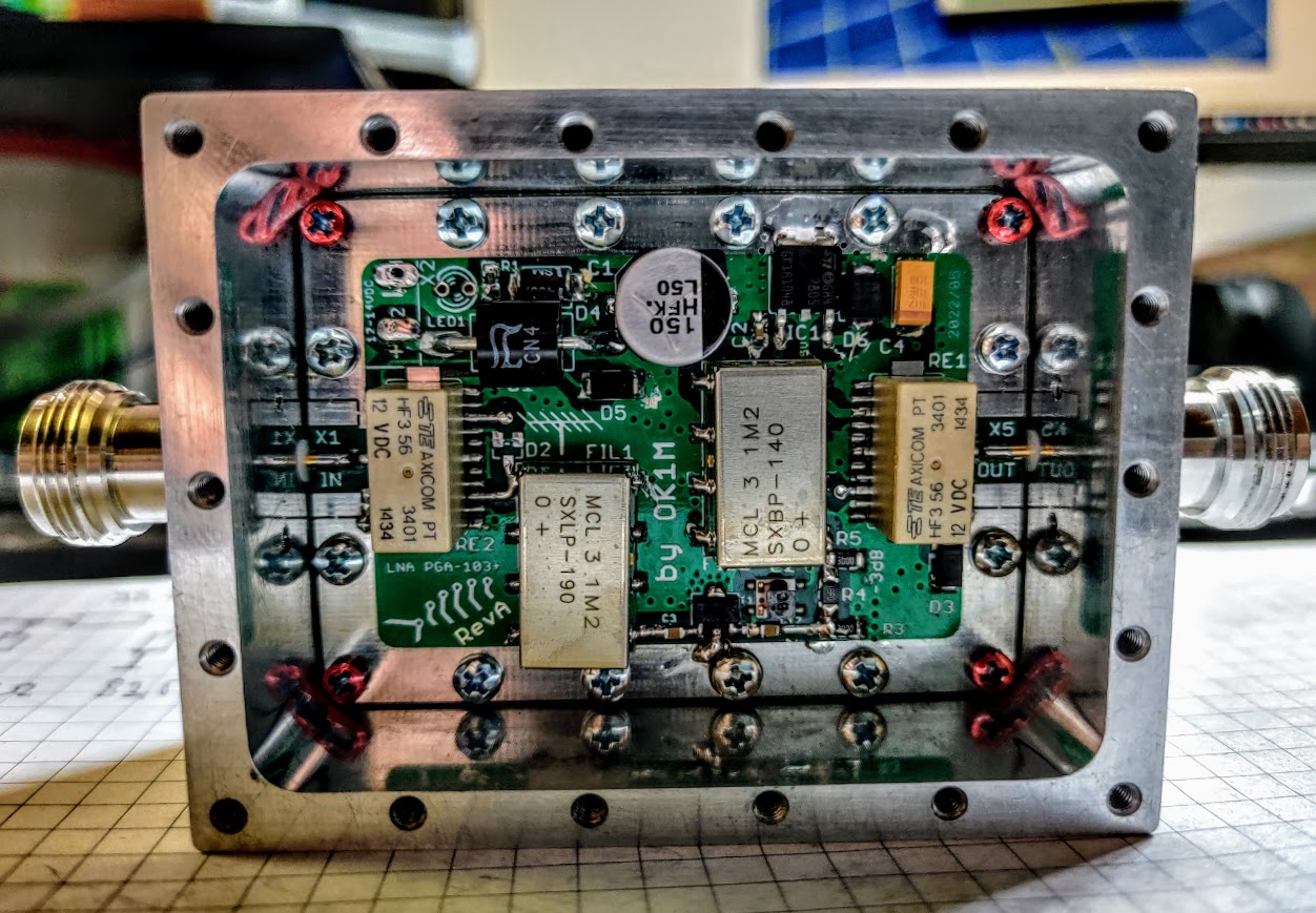
Signal path
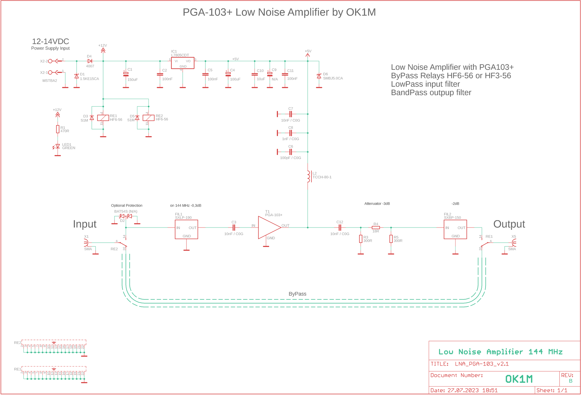
From the input, the signal passes through relay RE2 to the SXLP-190 low pass filter, the PGA-103+, a 3 dB attenuator and the band pass filter, then out through relay RE1. The schematic gives these losses at 144 MHz:
- Input low pass filter – 0.3 dB
- Attenuator after the amplifier – 3 dB (18 Ω and 2 × 300 Ω)
- Output band pass filter – 2 dB
The amplifier gets its 5 V through a TCCH-80+ choke, decoupled by 10 nF, 1 nF and 100 pF C0G capacitors. The pads for a BAT54S protection diode at the input are optional and it is not fitted.
Power supply and bypass
The preamplifier runs from 12–14 V DC. An L7805 regulator makes the 5 V for the amplifier, the relays run directly from 12 V and a green LED shows that power is on. The supply input is protected by a series 1N4007 diode and a 1.5KE15CA transil, the 5 V rail by an SMBJ5.0CA.
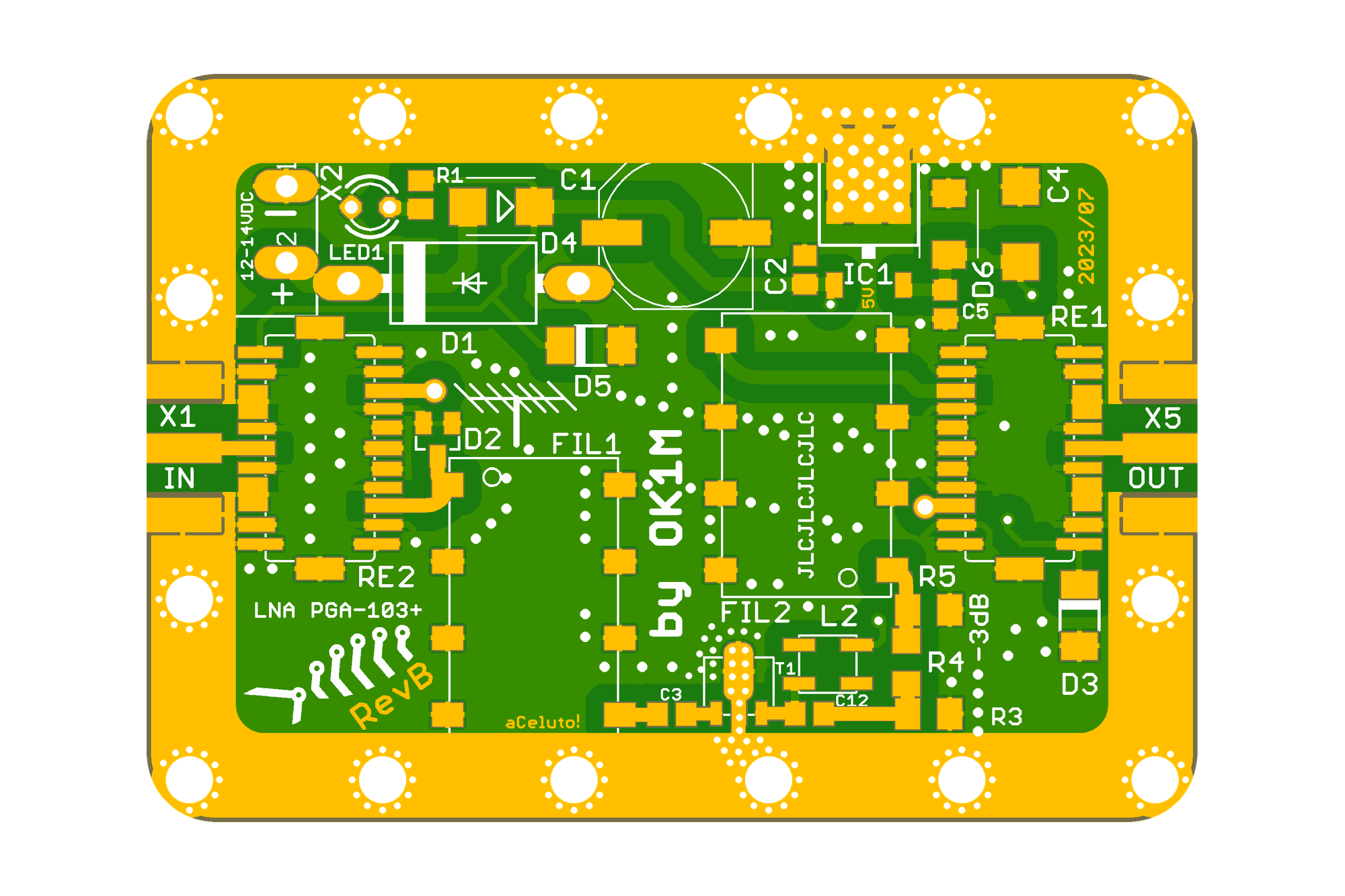
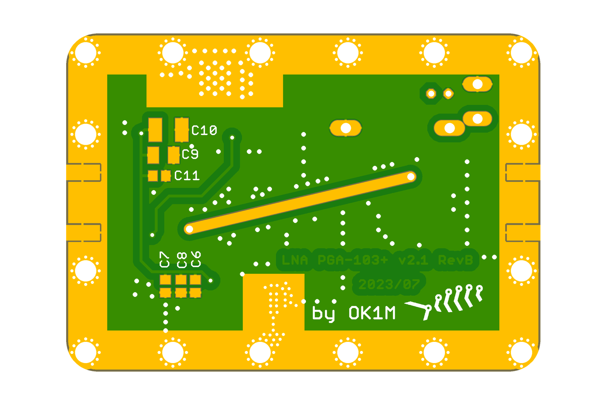
The relays are HF6-56 or HF3-56. The schematic shows them in the bypass position when not powered, so the signal then goes straight from input to output along a track on the bottom of the board.
Measurement
With the amplifier on, S21 reads 19.63 dB at 144.3 MHz. At 432.2 MHz the trace is at −53.5 dB, down in the noise floor of the measurement.
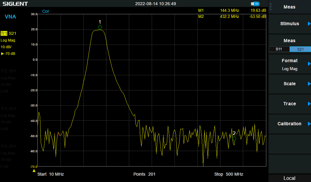
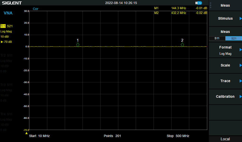
The photos and measurements show a unit with a 2022/05 board, an SXBP-140 output filter and HF3-56 relays. The schematic and PCB here are Rev B from 2023/07, which has the SXBP-150.
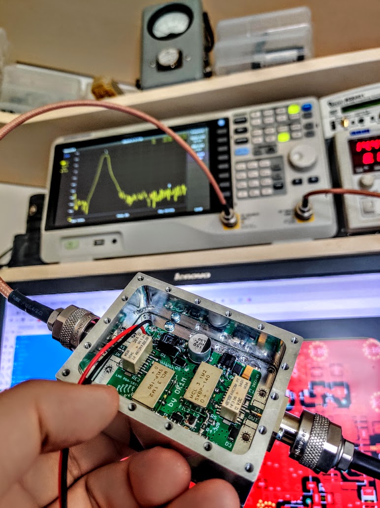
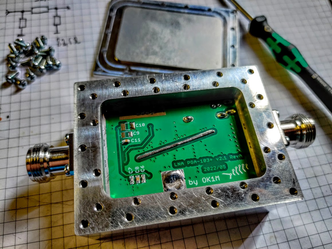
Schematic, board and gerbers: git.ok1kvk.cz/RybkaLabs/LNA-PGA-103-v2.1
73 & TNX